


AC Compressor Installation & Maintenance Manual
1. Safety Precautions
Air conditioning compressor service on heavy-duty commercial vehicles involves pressurised refrigerant, rotating engine-driven components, high-voltage clutch circuits, and heavy parts. Read this entire manual before beginning work. Only trained, qualified technicians using certified refrigerant recovery equipment should perform this procedure.
A/C systems operate under high pressure and contain refrigerant that can cause frostbite or eye injury on contact. Refrigerant must be recovered by a certified technician using approved recovery/recycling equipment before any line or compressor is disconnected. Never vent refrigerant to atmosphere — this is illegal in most jurisdictions and environmentally damaging.
Ensure the engine is switched off, the ignition key is removed, and the vehicle is secured (parking brake set, wheels chocked) before starting work. Allow the engine to cool before handling compressor mounting bolts and lines.
PAG (polyalkylene glycol) compressor oil is highly hygroscopic and will absorb moisture from the air rapidly. Keep containers sealed and minimise the time the system is open. Avoid skin and eye contact; refer to the product Safety Data Sheet (SDS).
General Precautions
- Wear safety glasses and refrigerant-resistant gloves throughout the procedure.
- Work in a well-ventilated area, away from open flame or hot surfaces — refrigerant can decompose into toxic gases when exposed to heat.
- Disconnect the vehicle battery negative terminal before disconnecting the compressor clutch electrical connector.
- Support the compressor securely when loosening mounting bolts — units can weigh 8–15 kg depending on model.
- Cap all open refrigerant lines and ports immediately to prevent moisture and debris ingress.
- Never operate the compressor without refrigerant charge or with the drive belt disconnected on a running engine.
- Dispose of used refrigerant, oil, and desiccant filters in accordance with local environmental regulations.
2. Tools & Materials Required
Tools
- Refrigerant recovery/recycling/charging station (certified, R134a or R404A as applicable)
- Manifold gauge set with quick-connect couplers
- Torque wrench (10–80 Nm range) with metric socket set
- Line wrenches / flare-nut wrenches (compressor port fittings)
- Belt tension gauge
- Vacuum pump (for system evacuation)
- Digital multimeter (clutch coil and connector testing)
- Compressor pulley/clutch puller set (model-specific)
- Clean lint-free rags and refrigerant-safe funnel
- Vehicle service jack and axle stands (if underside access required)
Materials
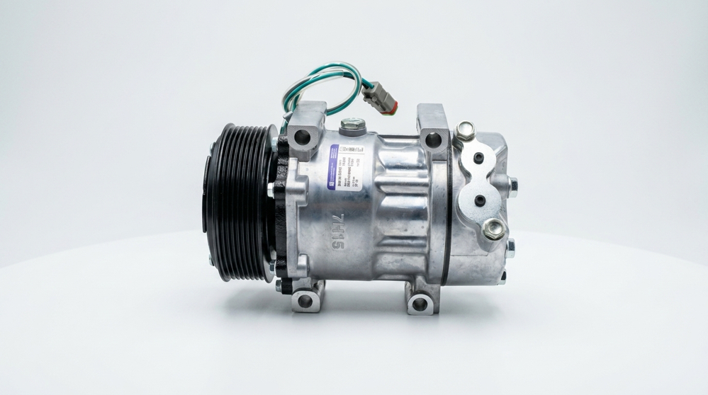
- BRW England replacement A/C compressor (correct part number for application)
- New O-ring seal kit (compressor-specific, correct refrigerant-compatible compound)
- PAG compressor oil (viscosity per OEM system specification — typically PAG 46 or PAG 100)
- Refrigerant (type and charge quantity per vehicle OEM specification)
- Replacement receiver-drier / accumulator (recommended whenever the system is opened)
- Threadlocker (medium strength, for mounting bolts where specified)
3. Pre-Installation Checks
Before fitting a new or replacement compressor, complete the following checks to prevent premature failure:
- Confirm the correct BRW part number and OEM cross-reference for the vehicle make, model, and engine variant.
- Inspect the drive belt and tensioner/idler pulleys for wear, glazing, or cracking — replace if degraded.
- Flush the system if metallic debris or excessive contamination is found from the failed compressor (see Section 7, Troubleshooting).
- Verify the correct oil type and quantity were drained from the old compressor; add the equivalent fresh PAG oil to the new unit before fitment (see Section 6).
- Inspect the condenser and evaporator for leaks, damage, or blockage — do not fit a new compressor onto a compromised system.
- Check the receiver-drier/accumulator; replace if the system has been open to atmosphere for more than a few hours or shows signs of moisture contamination.
- Confirm clutch air-gap specification and electrical connector condition.
4. Compressor Removal Procedure
- Connect the recovery station and fully recover the refrigerant charge from the system, recording the recovered quantity.
- Disconnect the vehicle battery negative terminal.
- Disconnect the compressor clutch electrical connector.
- Remove the drive belt from the compressor pulley (release tensioner per OEM procedure).
- Using line wrenches, disconnect the suction and discharge refrigerant lines at the compressor ports. Immediately cap both the compressor ports and the disconnected lines.
- Drain and measure the residual oil from the removed compressor into a clean, labelled container — record the quantity for reference when charging the new unit.
- Support the compressor weight, then remove the mounting bolts in a criss-cross pattern to avoid bracket distortion.
- Carefully withdraw the compressor from the mounting bracket. Inspect the bracket, pulley, and belt path for damage or debris.
- Inspect the removed compressor and residual oil for metal particles or discolouration — this indicates internal failure and confirms the need for a full system flush (see Section 7).
5. Compressor Installation Procedure
- Confirm the new BRW compressor part number matches the application before unpacking.
- Rotate the compressor clutch/pulley by hand through several full turns to distribute internal oil and confirm free rotation with no binding or unusual noise.
- Add fresh PAG oil to the new compressor to match the quantity drained from the old unit (Section 4, Step 6), adjusted for any oil retained in the condenser/evaporator per OEM guidance.
- Fit new O-rings (lightly lubricated with clean refrigerant oil) to all mounting and port connections — never reuse old O-rings.
- Position the compressor on the mounting bracket and hand-start all mounting bolts before torquing.
- Torque the mounting bolts to specification in a criss-cross sequence (see Section 6, Torque Specifications).
- Reconnect the suction and discharge refrigerant lines, torquing fittings to specification. Do not over-tighten flare fittings, as this can distort the sealing surface.
- Refit the drive belt and set tension to OEM specification using a belt tension gauge.
- Reconnect the compressor clutch electrical connector and verify a secure, corrosion-free connection.
- Reconnect the vehicle battery negative terminal.
- Evacuate the system using a vacuum pump for a minimum of 45 minutes, confirming the system holds vacuum for at least 15 minutes with no measurable rise (leak-free).
- Charge the system with the correct refrigerant type and quantity per the vehicle OEM specification.
- Start the engine, engage the A/C system, and verify clutch engagement, compressor operation, and correct high/low side pressures against OEM specification.
- Check all disturbed fittings for leaks using an electronic leak detector or UV dye method.
- Verify cold air output at the vents and confirm no abnormal noise or vibration from the compressor at idle and under load.
6. Torque Specifications & Fluid Capacities
The following torque values are general references for heavy-duty truck A/C compressor service. Where model-specific torque figures are published in the OEM workshop manual, those values take precedence.
| Fastener / Fitting | Torque Value | Notes |
|---|---|---|
| Compressor-to-bracket mounting bolts (M8) | 22 – 28 Nm | Criss-cross tightening sequence |
| Compressor-to-bracket mounting bolts (M10) | 40 – 50 Nm | Criss-cross tightening sequence |
| Suction line fitting (large port) | 20 – 25 Nm | Do not over-tighten flare fittings |
| Discharge line fitting (small port) | 18 – 22 Nm | Do not over-tighten flare fittings |
| Clutch retaining nut/bolt | 18 – 25 Nm | Model-dependent — verify OEM figure |
| Pulley/idler tensioner bolt | 45 – 60 Nm | Refer to OEM belt system manual |
Typical Fluid & Charge Reference
| Parameter | Typical Range | Notes |
|---|---|---|
| Refrigerant type | R134a (or R404A — legacy systems) | Confirm from vehicle data plate |
| Compressor oil type | PAG 46 / PAG 100 | Match viscosity to OEM system spec |
| Compressor oil charge | 150 – 250 ml | Varies by compressor model and system size |
| System refrigerant charge | 800 – 1800 g | Heavy-duty truck systems vary widely — always confirm OEM figure |
| Belt tension | Per OEM tensioner specification | Use auto-tensioner where fitted |
7. Troubleshooting Guide
| Symptom | Possible Cause | Recommended Action |
|---|---|---|
| Clutch does not engage | Blown fuse, faulty pressure switch, low refrigerant, wiring fault | Check fuses and relays; verify system pressure; test clutch coil resistance |
| Compressor noisy / knocking | Low oil level, worn internal components, loose mounting, worn clutch bearing | Check oil quantity; inspect mounting torque; replace compressor if internal wear confirmed |
| Insufficient cooling | Low refrigerant charge, blocked condenser, worn compressor, faulty expansion valve | Check system pressures against OEM spec; inspect condenser airflow; verify compressor output |
| Oil leakage at shaft seal | Worn shaft seal, contamination, incorrect O-ring fitment | Replace compressor or reseal per OEM procedure; verify correct O-ring compound |
| Metallic debris in system | Internal compressor failure | Full system flush required; replace receiver-drier/accumulator and orifice tube/expansion valve |
| Belt squeal or slip | Incorrect belt tension, glazed belt, misaligned pulley | Re-tension or replace belt; check pulley alignment |
| Rapid cycling on/off | Low refrigerant charge, faulty pressure switch, moisture in system | Check charge level; test pressure switch; evacuate and recharge if moisture suspected |
8. Warranty Information
BRW England A/C compressors are warranted against manufacturing defects for the period stated on the original invoice or as published on brwengland.com at the time of purchase. This warranty applies to the compressor unit only and is conditional upon correct installation, correct oil type/quantity, and adherence to the procedures set out in this manual.
Warranty Exclusions
- Damage resulting from installation without a full system flush after a prior compressor failure.
- Damage resulting from contamination, moisture ingress, or incorrect refrigerant/oil type.
- Damage caused by failure to replace the receiver-drier/accumulator where required.
- Damage resulting from incorrect belt tension, misalignment, or external impact.
- Normal wear items such as clutch bearings beyond the standard warranty period.
Claims Process
Warranty claims must be submitted with the original invoice, vehicle details, and a description of the failure mode. BRW England reserves the right to inspect the returned unit prior to approving a claim. Contact your BRW England account representative or visit brwengland.com for the current claims procedure.