


Air Compressor Installation & Service Manual
1. Safety Information
Fully depressurise the air brake system and release all air tank pressure before beginning work. Failure to do so can cause serious injury from sudden air discharge or component ejection.
Allow the engine and compressor to cool completely before handling. Surface temperatures can exceed 100°C after operation and may cause burns.
General Safety Requirements
- Park the vehicle on level ground, apply the parking brake, and chock the wheels.
- Disconnect the battery negative terminal before starting work.
- Drain all air reservoirs completely using the tank drain valves.
- Wear appropriate PPE: safety glasses, gloves, and steel-toe footwear.
- Use proper lifting equipment for components exceeding 10 kg.
- Never work under a vehicle supported only by a jack — use axle stands rated for the vehicle weight.
- Dispose of used coolant, oil, and gaskets in accordance with local environmental regulations.
2. Product Overview
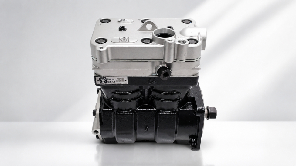
BRW England air compressors are engineered to OEM-equivalent specification for heavy duty truck and bus air brake and pneumatic accessory systems. This manual covers general installation practice applicable across the BRW compressor range, including single-cylinder, twin-cylinder, gear-driven, and belt-driven variants.
Compressor Types Covered
- Single-cylinder, gear-driven (engine timing gear mounted)
- Twin-cylinder, gear-driven (high-output applications)
- Belt-driven compressors (front engine accessory mount)
- Coolant-cooled and air-cooled cylinder head variants
Always confirm the exact BRW part number and OEM cross-reference against your vehicle's chassis number and original compressor before installation. Refer to Section 12 for cross-reference guidance.
3. Tools & Materials Required
| Category | Item |
|---|---|
| Hand Tools | Metric socket set (10–24 mm), torque wrench (10–200 Nm), ratchet, breaker bar |
| Hand Tools | Hex key set, flat & Phillips screwdrivers, oil filter strap wrench |
| Lifting | Engine hoist or support bracket (for gear-driven units), trolley jack, axle stands |
| Consumables | New compressor gasket set, O-rings, coolant hose clamps, thread sealant (if specified) |
| Fluids | Engine oil (per OEM spec), coolant (per OEM spec — coolant-cooled units only) |
| Test Equipment | Air pressure gauge, leak-detection spray, digital multimeter (for solenoid/sensor checks) |
| Safety | PPE — gloves, safety glasses, drain pan |
4. Pre-Installation Checklist
- Confirm the replacement BRW compressor part number matches the OEM cross-reference for the vehicle (chassis/engine number).
- Inspect the new compressor for shipping damage before installation.
- Confirm cylinder head configuration (coolant-cooled vs air-cooled) matches the outgoing unit.
- Verify drive type (gear-driven vs belt-driven) and mounting flange bolt pattern match.
- Gather all new gaskets, O-rings, and seals — do not reuse old gaskets.
Note governor cut-in/cut-out settings and unloader valve type on the outgoing unit for reference.
5. Removal of Old / Faulty Compressor
- Depressurise the full air system via the tank drain valves. Confirm 0 psi on the dash gauge.
- Disconnect the vehicle battery negative terminal.
- Drain engine coolant if the compressor is coolant-cooled, into a suitable container.
- Label and disconnect the air discharge line, governor line, and any unloader/solenoid connections.
- Disconnect coolant supply and return lines (coolant-cooled units).
- Disconnect the oil supply line and, on wet-sump gear-driven units, the oil return/drain line.
- Remove the drive belt (belt-driven units) or disengage the timing gear coupling (gear-driven units).
- Support the compressor weight, then remove the mounting bolts and lift the unit clear.
- Remove and discard the old gasket. Clean the mounting face on the engine block thoroughly.
6. Installation Procedure
Torque values in this section are general guidance. Always confirm against the OEM service manual for the specific engine model — see Section 7 for the BRW reference torque table.
- Confirm the engine mounting face and gasket surface are clean, dry, and free of old gasket material.
- Fit a new gasket to the compressor mounting flange — do not use sealant unless specified by OEM.
- Lubricate the drive gear or coupling with clean engine oil prior to fitment (gear-driven units).
- Position the compressor onto the mounting studs/bolts, engaging the drive gear or belt pulley squarely.
- Hand-tighten all mounting bolts first, then torque in a diagonal (criss-cross) sequence to the value specified in Section 7.
- Reconnect the oil supply line and, where fitted, the oil drain/return line. Torque banjo bolts to spec — do not overtighten copper washers.
- Reconnect coolant supply and return lines (coolant-cooled units) and refit hose clamps.
- Reconnect the air discharge line, governor line, and unloader/solenoid connections per the labels made during removal.
- Refit and correctly tension the drive belt (belt-driven units) per OEM belt tension specification.
- Refill engine coolant to the correct level (coolant-cooled units) and bleed the cooling system per OEM procedure.
- Reconnect the vehicle battery negative terminal.
7. Torque Specifications
| Fastener / Connection | Torque Value | Notes |
|---|---|---|
| Compressor mounting bolts (M10) | 45–55 Nm | Tighten in diagonal sequence |
| Compressor mounting bolts (M12) | 80–95 Nm | Tighten in diagonal sequence |
| Cylinder head bolts | 25–30 Nm | Follow OEM tightening sequence |
| Oil supply banjo bolt | 25–35 Nm | Replace copper sealing washers |
| Oil drain/return line fitting | 20–25 Nm | Do not overtighten — aluminium threads |
| Coolant line fittings | 15–20 Nm | Hand-tight plus 1/4 turn on hose clamps |
| Air discharge line fitting | 30–40 Nm | Check for thread damage before fitting |
| Governor mounting bolts | 18–22 Nm | — |
| Drive pulley retaining nut (belt-driven) | 90–110 Nm | Hold pulley with strap wrench, not gear teeth |
8. System Priming & Leak Testing
- Check engine oil level and top up if required — compressor lubrication draws from the engine sump on most gear-driven units.
- Start the engine and allow it to idle. Do not rev the engine until oil pressure is confirmed.
- Listen for unusual knocking, whining, or grinding noises from the compressor — stop immediately if detected.
- Apply leak-detection spray to all new fittings: oil lines, coolant lines, and the discharge line.
- Check for coolant leaks at the cylinder head and hose connections (coolant-cooled units).
- Allow the system to build air pressure and confirm no audible air leaks at the discharge fitting or unloader valve.
9. Commissioning & Functional Check
- With the engine running, allow the air system to build pressure from empty to full governor cut-out.
- Confirm governor cut-out pressure matches OEM specification (typically 120–135 psi / 8.3–9.3 bar — confirm against vehicle spec plate).
- Confirm governor cut-in pressure matches OEM specification (typically 100–110 psi / 6.9–7.6 bar).
- Verify the unloader valve vents correctly at cut-out (audible discharge from the compressor exhaust port).
- Check dash warning lamps/buzzers clear once system pressure exceeds the low-air-pressure threshold.
- Road test the vehicle and recheck all fittings for leaks after the compressor reaches normal operating temperature.
10. Troubleshooting Guide
| Symptom | Possible Cause | Corrective Action |
|---|---|---|
| Slow air build-up | Worn piston rings / valves; drive belt slipping | Check compressor output; inspect/replace belt tension |
| Excessive oil consumption | Worn piston rings; blocked oil return line | Inspect rings; clear or replace oil drain line |
| Compressor overheating | Low coolant flow; blocked cooling passages | Check coolant lines and flow; flush cooling passages |
| Knocking noise | Worn crankshaft bearing; loose drive coupling | Inspect drive coupling; replace compressor if bearing worn |
| Air in discharge line has oil carryover | Worn rings; incorrect oil grade; overfilled sump | Check oil level/grade; inspect ring wear |
| Governor will not cut out | Faulty governor; blocked governor line | Clean/replace governor; check line for blockage |
| No air output | Sheared drive gear; seized cylinder; blocked inlet | Inspect drive coupling; check air filter/inlet for blockage |
| Coolant leak at compressor | Damaged gasket; loose hose clamp | Replace gasket; retighten or replace clamp |
11. Maintenance Schedule
| Interval | Task |
|---|---|
| Daily | Drain air tanks; check for audible air leaks |
| Every 20,000 km / 3 months | Inspect drive belt condition and tension (belt-driven units) |
| Every 40,000 km / 6 months | Inspect coolant and oil lines for chafing or leaks |
| Every 80,000 km / 12 months | Check governor cut-in/cut-out pressures; inspect unloader valve operation |
| Every 160,000 km / 24 months | Full compressor output test; inspect mounting bolt torque |
12. OEM Cross-Reference
BRW England air compressors are manufactured to match OEM fit, form, and function. Always confirm the correct part number against your specific chassis and engine code before ordering.
| OEM Brand | Typical Platforms Covered |
|---|---|
| Volvo / Renault Trucks | FH, FM, FE series; Renault D, T, C series (Volvo-derived engines) |
| Mercedes-Benz | Actros, Axor, Atego series |
| Scania | P, G, R, S series |
| MAN | TGX, TGS, TGM series |
| DAF | XF, CF, LF series |
| IVECO | Stralis, Trakker, Eurocargo series |
13. Warranty & Contact
BRW England air compressors are covered under the standard BRW England aftermarket parts warranty against manufacturing defects. Warranty does not cover damage resulting from incorrect installation, contaminated fluids, or failure to follow the torque and commissioning procedures outlined in this manual.