


Water Pump — Installation & Maintenance Manual
1. Introduction & Scope
This manual provides general installation and maintenance guidance for BRW England heavy-duty water pumps fitted to commercial vehicle diesel engines. It covers removal, inspection, installation, torque specifications, coolant system refilling, and troubleshooting applicable across the BRW water pump range.
This is a general manual. Where a part-specific installation manual exists for the exact BRW part number and OEM reference fitted to the vehicle, that document takes precedence for torque values, bolt patterns, and engine-specific notes. Always cross-check with the relevant OEM workshop manual for the engine family being serviced.
This manual is intended for use by trained and qualified heavy-duty vehicle technicians only. Read this manual in full, together with the vehicle/engine manufacturer's workshop manual, before beginning work.
2. Safety Precautions
Never open a cooling system radiator or expansion tank cap while the engine is hot or under pressure. Escaping pressurised coolant can cause severe scalding. Allow the engine to cool fully before starting work.
- Park the vehicle on level ground, apply the parking brake, and chock the wheels before starting any work.
- Allow the engine to cool to ambient temperature before draining coolant or removing the water pump.
- Disconnect the battery negative terminal before working near the engine to prevent accidental starting.
- Wear appropriate PPE: safety glasses, cut-resistant gloves, and coolant-resistant gloves when handling used coolant.
- Used engine coolant is hazardous to the environment and toxic if ingested. Collect and dispose of it in accordance with local environmental regulations.
- Support the vehicle on approved axle stands if working underneath; never rely on a jack alone.
- Relieve drive belt tension fully before removing the water pump pulley.
- Use lifting equipment rated for the component weight where the water pump assembly is heavy or awkward to handle.
- Do not run the engine with the radiator cap removed or with coolant hoses disconnected.
- Ensure all tools are in good condition and rated for the torque values specified in Section 9.
3. Tools & Materials Required
3.1 Tools
- Metric socket and spanner set (typically 10–19 mm, confirm against engine-specific fasteners)
- Torque wrench (calibrated, suitable range for engine's fastener specification)
- Drive belt tensioner tool (manual or hydraulic, per engine type)
- Coolant drain pan (minimum capacity to match engine cooling system volume)
- Gasket scraper / plastic scraper (for aluminium mating surfaces)
- Wire brush or fine abrasive pad (for cleaning mating surfaces)
- Torque angle gauge (if bolts specify angle-tightening)
- Pry bar / soft-faced mallet (for careful pump separation, if seized)
- Coolant refractometer or hydrometer (to verify coolant mix ratio)
- Refilling / vacuum coolant filling equipment (recommended for closed systems with bleed screws)
3.2 Materials
- BRW replacement water pump (correct part number for engine application)
- New water pump gasket or O-ring (do not reuse old gasket)
- Fresh coolant — correct type and concentration per OEM specification (e.g. OAT/HOAT, ready-mix or concentrate diluted to spec)
- Thread-locking compound (only where specified by OEM — check bolt-specific requirement)
- Clean lint-free cloths
- Anti-seize compound (for pulley bolt threads where specified)
4. Water Pump Overview
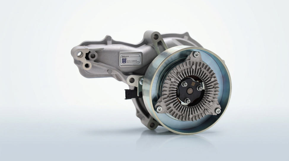
The water pump circulates coolant through the engine block, cylinder head, radiator, and heater circuit to maintain optimal operating temperature. On heavy-duty diesel engines it is typically belt-driven or gear-driven from the front of the engine and may also drive or be co-located with the cooling fan hub.
BRW heavy-duty water pumps are manufactured to OEM-equivalent specification with mechanical seal, bearing assembly, and impeller matched to the original engine cooling requirements. Key components typically include:
- Pump housing (cast iron or aluminium, application-dependent)
- Impeller (stamped steel, cast, or composite depending on application)
- Shaft and sealed bearing unit
- Mechanical seal (carbon/ceramic face seal)
- Drive pulley or gear (belt-driven or gear-driven variants)
- Mounting gasket or integrated O-ring seal
5. Pre-Removal Checks
- Confirm the correct replacement part number against the vehicle's chassis/engine number and OEM cross-reference before starting work.
- Inspect for visible coolant leakage, staining, or weep-hole discharge at the old water pump to confirm failure mode.
- Check drive belt condition and tensioner operation — a failing tensioner can cause premature pump bearing wear.
- Note the routing of the drive belt (photograph it) before removal if the belt is being disturbed.
- Verify coolant type and capacity for the engine from the OEM manual before draining.
6. Removal Procedure
Steps below are general. Fastener count, access panels, and ancillary components (fan shroud, alternator, AC compressor bracket) vary by engine make and model — refer to the OEM workshop manual for exact clearance requirements.
- Disconnect the battery negative terminal.
- Allow the engine to cool completely, then open the radiator/expansion tank cap slowly to release residual pressure.
- Position a drain pan beneath the radiator drain cock or engine block drain plug and drain the coolant fully.
- Release drive belt tension using the tensioner tool and remove the belt from the water pump pulley. Note routing.
- Remove any ancillary brackets, fan shroud, or hoses obstructing access to the water pump (e.g. alternator bracket, AC compressor bracket, coolant hoses).
- Disconnect all coolant hoses from the water pump housing, marking their positions if not obvious.
- Remove the water pump pulley retaining bolts (if pulley is separate from the pump body) and remove the pulley.
- Remove the water pump mounting bolts in a criss-cross sequence to avoid distorting the housing.
- Carefully separate the water pump from the engine block or timing cover. If seized, use a soft-faced mallet or pry point cast into the housing — never pry against the gasket sealing face.
- Remove and discard the old gasket or O-ring completely from both mating surfaces.
7. Inspection Before Installation
- Clean the mating surface on the engine block/timing cover thoroughly — remove all old gasket material without gouging the aluminium surface.
- Inspect the mating surface for flatness, corrosion pitting, or damage that could prevent a proper seal.
- Inspect coolant passages in the block for blockage, scale build-up, or debris; flush if necessary.
- Check the drive belt, tensioner, and idler pulleys for wear — replace as a set if the belt has failed or shows glazing/cracking.
- Confirm the new BRW water pump part number matches the removed unit and OEM cross-reference exactly.
- Rotate the new pump shaft by hand to confirm free, smooth rotation with no bearing roughness or seal leakage before fitting.
8. Installation Procedure
- Fit a new gasket or O-ring dry (unless the OEM specifies a sealant) — do not reuse the old gasket.
- Position the new BRW water pump onto the mounting face, aligning bolt holes and any locating dowels.
- Install mounting bolts finger-tight first, then tighten in a criss-cross (star) pattern to the torque specification in Section 9.
- Refit the water pump pulley (if separate) and tighten retaining bolts to specification.
- Reconnect all coolant hoses to their marked positions and secure clamps to correct torque/clamp tension.
- Refit ancillary brackets, fan shroud, and any components removed for access.
- Refit the drive belt following the noted routing and release the tensioner to apply correct belt tension.
- Rotate the engine by hand (where safely possible) to confirm the pulley and belt run true with no interference.
9. Torque Specifications
Torque values above are general reference figures for heavy-duty diesel applications. Always use the exact torque and tightening sequence specified in the engine manufacturer's workshop manual or the BRW part-specific installation manual when available.
| Fastener | Thread Size (typical) | Torque (Nm) | Notes |
|---|---|---|---|
| Water pump housing bolts | M8 | 22–25 | Criss-cross sequence; refer to OEM manual if angle-tightening specified |
| Water pump housing bolts | M10 | 44–48 | Criss-cross sequence |
| Pump pulley retaining bolts | M8 | 23–26 | Apply anti-seize if specified by OEM |
| Coolant hose clamps (worm-drive) | — | 4–6 | Do not over-tighten; risk of hose damage |
| Fan shroud / bracket fasteners | M8 | 18–22 | Reinstall per OEM torque where available |
10. Coolant Refill & System Bleeding
- Close all drain cocks/plugs before refilling.
- Refill with the correct coolant type and concentration specified by the OEM (typically 50:50 mix unless the manufacturer specifies otherwise) — check freeze protection rating for the operating climate.
- Fill slowly via the radiator/expansion tank filler to reduce air pockets, opening any bleed screws present until a steady coolant stream (no air) is observed, then close them.
- Fill to the correct level mark on the expansion tank — do not overfill.
- Leave the filler cap off (or loosely seated, if the design allows) and run the engine at idle with the heater set to maximum to help purge trapped air, per OEM procedure.
- Top up coolant level as it drops during the bleeding process, then fit the filler cap securely once air is purged.
11. Post-Installation Checks & Running Test
- Reconnect the battery negative terminal.
- Start the engine and check immediately for coolant leaks at the pump housing, hose connections, and gasket face.
- Run the engine to normal operating temperature and confirm the thermostat opens and the cooling fan engages correctly.
- Check belt tracking and tension after a short run; re-check tensioner operation.
- Recheck coolant level once the system has fully warmed and cooled, topping up as required.
- Road test the vehicle where possible and recheck for leaks and correct operating temperature after the test.
12. Troubleshooting Guide
| Symptom | Possible Cause | Recommended Action |
|---|---|---|
| Coolant leak from weep hole | Mechanical seal failure | Replace water pump; inspect for coolant chemistry issues that may have degraded seal |
| Coolant leak at housing gasket | Damaged gasket / mating surface / under-torqued bolts | Replace gasket, inspect mating surface flatness, re-torque to spec |
| Engine overheating | Impeller failure, worn bearing, low coolant, blocked passages | Inspect impeller condition, check coolant level and flow, flush cooling system if blocked |
| Grinding or squealing noise from pump area | Worn/failing bearing, belt misalignment, insufficient belt tension | Replace pump if bearing is worn; check belt alignment and tensioner |
| Pulley wobble | Bent pulley, worn bearing, incorrect installation torque | Inspect pulley and shaft; re-torque or replace as needed |
| Air in cooling system after service | Incomplete bleeding procedure | Repeat bleed procedure per Section 10; check for a faulty bleed screw seal |
| Premature pump failure (repeat) | Incorrect coolant type/concentration, contaminated coolant, over-tensioned belt | Verify coolant spec, flush and refill system, check belt tension against OEM spec |
13. Maintenance Interval Recommendations
- Visually inspect the water pump for leaks, weep-hole discharge, and belt condition at every scheduled service interval.
- Check coolant condition, concentration, and level at every scheduled service interval; test with a refractometer where possible.
- Replace coolant per the OEM-specified interval (varies by coolant type — conventional vs long-life OAT/HOAT formulations).
- Inspect drive belt and tensioner condition at every service; replace belt per OEM interval or at first sign of cracking/glazing.
- As a preventative measure on high-mileage/high-hour engines, consider replacing the water pump proactively during major engine service work (e.g. timing belt/chain service) even if not yet failed.
14. Warranty Information
BRW England water pumps are covered under the standard BRW England aftermarket parts warranty against manufacturing defects, subject to correct installation, correct application, and use of genuine coolant meeting OEM specification.
Warranty claims may be affected by, and BRW England reserves the right to reject claims arising from, the following:
- Incorrect installation torque or procedure not following this manual or the OEM workshop manual
- Use of incorrect or contaminated coolant, or incorrect coolant concentration
- Installation of an incorrect part number for the application
- Damage caused by a failed drive belt, tensioner, or other ancillary component not replaced at the time of installation
- Operation of the vehicle with a known coolant leak or overheating condition prior to failure
For warranty claims, contact your BRW England distributor or the BRW England technical support team with the part number, chassis/engine number, proof of purchase, and a description of the failure mode.