Reading Time: 4 Minutes
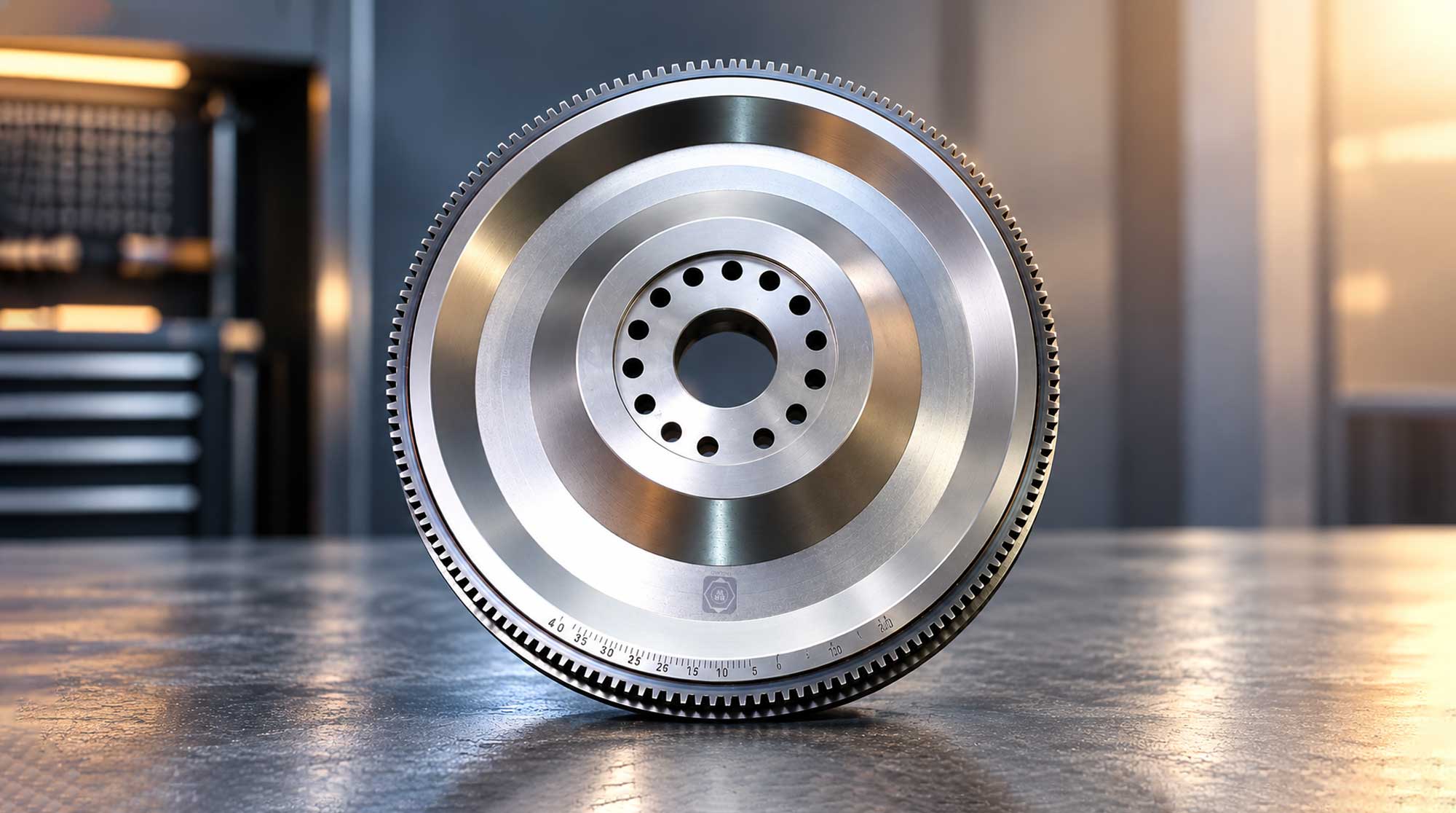
Working behind the engine and clutch assembly, the flywheel helps stabilise crankshaft rotation, supports smooth power transmission and enables reliable engine starting in heavy-duty commercial vehicles.
A heavy-duty truck engine does not deliver power as a perfectly continuous rotational force. It delivers it in pulses, one for each power stroke. The flywheel is what turns that surge and lull into something a gearbox can live with.
Mounted at the rear of the crankshaft, it rotates in step with the engine. It is easy to overlook in routine maintenance, yet it shapes engine-speed stability, clutch performance and dependable starting.
WHERE THE FLYWHEEL FITS
The flywheel sits between the engine and the clutch. Power flows from the crankshaft into the flywheel, across the clutch and on to the transmission:
ENGINE → FLYWHEEL → CLUTCH → TRANSMISSION
That position explains why it matters twice over. It smooths the engine’s output, and it also forms the working surface against which the clutch operates.
WHY THIS MATTERS
For commercial vehicles working under heavy loads, long schedules and demanding conditions, a correctly specified and well-maintained flywheel contributes directly to drivetrain reliability. When one fails, the symptoms tend to appear elsewhere, as judder, vibration or starting trouble, and the repair usually involves the clutch and substantial workshop time. For a fleet, that means downtime and repeat repairs.
WHAT THE FLYWHEEL DOES
Smoothing the power pulses. During each power stroke, the engine drives energy into the crankshaft and flywheel. The flywheel stores part of it as rotational kinetic energy and returns it between strokes, reducing fluctuations in crankshaft speed and making the engine run more evenly.
Providing the clutch surface. In a conventional manual-transmission clutch, the flywheel supplies the friction surface the clutch disc engages. When the clutch is engaged, friction carries engine torque through the assembly to the gearbox. When it is disengaged, the connection is broken so the driver can change gear. The surface has to be flat and within the manufacturer’s tolerances to support consistent engagement and limit heat and uneven wear.
Starting the engine. In many designs, a toothed ring gear around the rim meshes with the starter pinion and turns the crankshaft until the engine fires. Damaged or heavily worn teeth can interfere with starter engagement, causing abnormal noises or starting difficulties.
SOLID OR DUAL-MASS
The flywheel’s fourth job, managing torsional vibration, depends on its design.
A solid flywheel is a single rigid component that provides rotational inertia and, in manual applications, the clutch friction surface. Its relatively simple construction makes it widely used in commercial vehicles. A dual-mass flywheel (DMF) splits the mass in two, joined by an internal spring-and-damping arrangement that isolates torsional vibration before it reaches the gearbox, reducing drivetrain noise and improving refinement.
Heavy trucks have traditionally used solid flywheels, and a 2018 Chalmers University of Technology study of truck powertrains, carried out in a project involving AB Volvo and Scania, described DMF use in heavy-duty applications as very limited to date. It also found that flywheel and clutch properties must be matched to the powertrain if vibration is to be isolated across the full speed and torque range.
The two designs are not automatically interchangeable. The vehicle manufacturer’s engineering specification sets the right choice, and any conversion must be approved for the specific engine, clutch and transmission.
MATERIALS, MACHINING AND PRECISION
Heavy-duty flywheels are commonly made from suitable grades of cast iron or steel, chosen for the design and the mechanical properties it requires. Strength alone is not enough. Accurate machining, correct mounting dimensions, controlled run-out and proper balancing are essential for stable rotation and alignment with the crankshaft and clutch.
The friction surface, mounting face, bolt holes and ring gear must all meet specification. Incorrect machining, unsuitable replacement parts or poor installation can contribute to vibration, clutch problems and premature failure.
RECOGNISING WEAR AND FAILURE
Flywheel problems can develop gradually, or come to light after clutch damage, overheating or incorrect installation. Workshop inspection is especially valuable when clutch or transmission repairs expose the component. Signs to watch for include:
- Clutch judder. Vibration or uneven engagement when pulling away.
- Drivetrain vibration. Rotational fluctuations that become noticeable at particular speeds or loads.
- Unusual noises. Rattling, clattering or metallic sounds during starting, idling, gear changes or shutdown, particularly with a dual-mass flywheel.
- Starting difficulties. Grinding or inconsistent starter engagement where the ring gear or starter system is damaged.
- Visible surface damage. Heat spots, scoring, cracks, distortion or excessive wear on the friction surface.
None of these confirms flywheel failure on its own. The clutch, starter motor, engine and transmission mountings, bearings and other drivetrain parts can produce similar signs, so correct diagnosis comes before any replacement.
MAINTENANCE THAT PROTECTS PERFORMANCE
A flywheel is not normally replaced at every clutch service, but its condition should be assessed whenever the clutch or gearbox is removed. A thorough inspection covers the friction surface, ring gear teeth, mounting face, bolt holes and any evidence of overheating, cracks or excessive run-out.
Resurfacing may be permitted for certain solid flywheels when wear is within repairable limits, provided the manufacturer allows it and the specified minimum thickness, surface geometry and other dimensions can be maintained. Cracked or otherwise unserviceable components must never be returned to service.
A dual-mass flywheel needs design-specific checks in line with the manufacturer’s procedures, and it is generally replaced as a complete assembly when it fails them. Replacing the clutch at the same time may be appropriate, depending on its condition and the manufacturer’s recommendations.
Driving habits count too. Prolonged clutch slipping, repeated harsh engagement, excessive heat and unsuitable operating conditions all add stress to the flywheel and its neighbouring components.
WHY THE RIGHT REPLACEMENT MATTERS
Choosing a replacement takes more than matching its outward appearance. Engine model, crankshaft mounting dimensions, ring gear specification, clutch configuration, transmission type and the original equipment manufacturer’s requirements must all be considered.
A correctly specified replacement supports dependable starting, consistent clutch engagement and smooth power transmission. Incorrect fitment can introduce alignment problems, abnormal vibration, premature wear or damage to connected components. For fleet operators, workshops and distributors, accurate identification before ordering is the best protection against avoidable downtime and repeat repairs.
emBRWace Perspective
The flywheel is hidden from view throughout everyday operation, but its influence runs across the engine, clutch and transmission. It is one of those components whose value is measured by what does not happen: no judder, no starting trouble, no vibration travelling down the drivetrain.
For heavy-duty fleets, that argues for treating it as part of the clutch system’s health, not an afterthought. Inspecting it whenever the clutch is open, specifying it correctly and diagnosing before replacing are the habits that protect component life and vehicle availability.
The flywheel is more than a rotating mass. It is a vital link between engine operation and effective power transmission.
emBRWace Explains
Flywheel
A heavy rotating component mounted on the crankshaft that smooths the engine’s power pulses, provides the clutch friction surface and carries the ring gear used for starting.
Rotational kinetic energy
The energy a spinning object stores. The flywheel absorbs it during power strokes and releases it between them.
Ring gear
A toothed ring around the flywheel’s rim that meshes with the starter motor’s pinion to turn the engine over.
Torsional vibration
Twisting fluctuations in rotational speed that travel through the drivetrain and can cause noise, wear and damage if not damped.
Dual-mass flywheel (DMF)
A flywheel made of two masses joined by an internal spring-and-damping arrangement that isolates torsional vibration from the gearbox.
Run-out
The amount by which a rotating surface wobbles away from a true, flat plane, which must stay within the manufacturer’s limits.
Thought to Take Away
A flywheel does not create power. It makes power smooth enough to use.
Sources: Flywheel technical brief (supplied document); Chalmers University of Technology, Dual mass flywheels in truck powertrains: Modelling, simulations and validation (2018)